
How to make house wiring electric men board ।। Electrical board YouTube
PCB is an acronym for printed circuit board. It is a board that has lines and pads that connect various points together. In the picture above, there are traces that electrically connect the various connectors and components to each other. A PCB allows signals and power to be routed between physical devices.
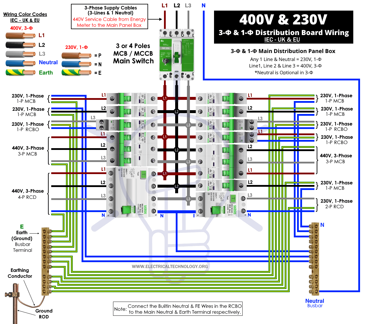
Three Phase Electrical Wiring Installation in Home NEC & IEC
https://toolsreview.us/ Electric Board Wiring Connection ,socket , switch Indicator lamp,fuse,fan point,lighting point 7 way BoardPLEASE SUBSCRIBE MY NEW CHA.
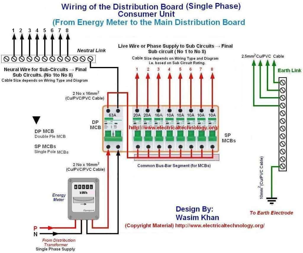
Wiring of the distribution board , Single phase, from Energy meter to the main distribution
L i k e Share Save 6.1M views 6 years ago #ElectricBoardConnection #Auzaarnow Learn How To Make An Electric Extension Board with 2 Socket 2 Switch Electric Board connection. In this video, we.
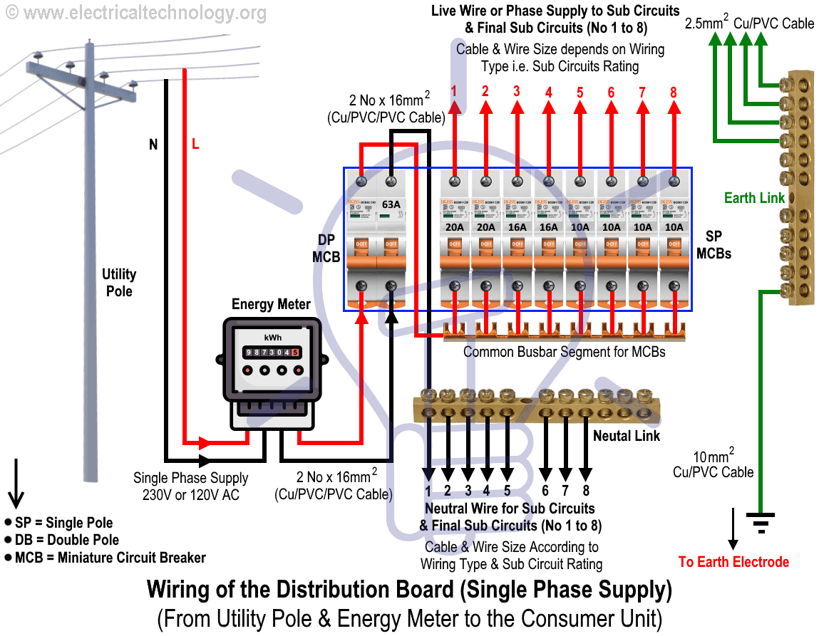
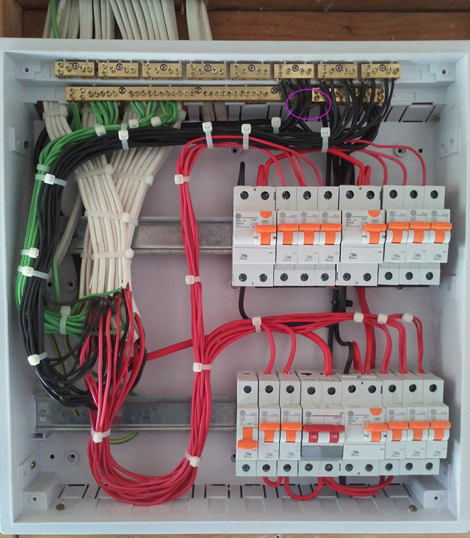
Wiring of the Distribution Board From Energy Meter to the Consumer Unit
Distribution Board or DB is an electricity supply system or a common enclosure that distributes the electrical power feed into subcircuits. It includes isolator, RCCB (Residual current circuit breaker) or RCD (Residual-current device) devices, protective fuses or MCB's (Miniature Circuit Breaker) for each subcircuit, etc.

Electric Board Wiring Connection 1 Socket 4 Switch Board YouTube
#BEEEWorks #Electricalwork #wiring Hello Friends ! Welcome back to our channel. I hope this video may helps you 😊🔴 Red wire = Phase ⚫ Black wire =.

How to make electric board Electric Board wiring connection 1 Socket 1 Switch Electric Board
It is used for most interior circuits, such as those for outlets, switches, light fixtures, and appliances. Learn the basics of NM cable to choose the right type for your next electrical project. Electrical Wire Color Coding The Spruce / Margot Cavin

Electrical Extension Board Wiring Diagram
Abstract: More and more printed circuit boards (PCBs) will be used in electric aircraft to achieve higher power density of the on-board electric system, while PCBs in aircraft are more likely to generate partial discharges (PDs) due to external factors such as compact structure and low air pressure. Therefore, this paper proposes a fluorescent fiber-based method for detecting and evaluating.

All That You Need to Know About Distribution Boards (DB) Engineering Discoveries
Switch box wiring or switchboard wiring is a common wiring arrangement used in most house electrical wirings or switchboards. The given circuit is a basic switchboard wiring for a light switch (one lamp controlled by one switch) and 3 pin plug socket with control switch. How to wire up a switchboard
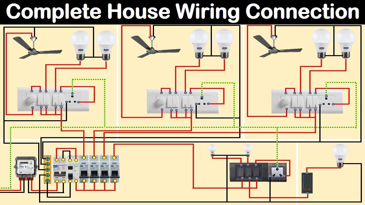
Complete House Wiring Diagram with main distribution board house wiring Electrical
Document. LJL Liman Policy on the Use of Electronic Devices_FINAL.pdf 16.69 KB.

Electrical Board Wiring Fiting YouTube
The Spruce / Kevin Norris. One 15- to 20-circuit breaker box. $700 to $950 (labor not included) This overview describes how a professional electrician connects a residential electrical circuit breaker panel to the main service wires coming into the home, and to the individual branch circuits in your home. In almost every situation, this will be.

House Wiring of Main Electrical Board Step by Step
When it comes to electrical wiring, connecting wires to a circuit board is an important skill for any electrician to have. It can be a complex and confusing task, but with the right tools and knowledge, anyone can learn how to connect wires to a circuit board and complete an installation safely and efficiently.

Electric board wiring YouTube
Common Electrical Panel Sizes. There are different types of electrical panel boards that provide 100, 200, or more amps of power to a home. An amp is short for ampere, which is a standard unit of measurement of an electrical current. Homes built between 1950 and 1965 may have these 60-ampere fuse boxes, often with just four fuses.

How to the electric board wiring ! Home ! videos YouTube
A wiring diagram is a simplified representation of the conductors (wires) and components (devices, lights, motors, switches, sensors and more) that make up an electrical circuit or electrical system.

Electrical Switchboard Connection more wiring
Three Phase 208 AC: Grey= Phase 1 or Line1, Black= Line 2, Brown= Line 3, Blue = Neutral and Green= Earth Conductor. Below is the given wiring diagram of Single Phase Distribution Board with RCD in both NEC and IEC electrical wiring color codes. The same description and detailes can be used as mentioned for the above fig 1.
main switch board wiring diagram Wiring Diagram and Schematics
Drill into Corners at an Angle. Angle the bit into tight spots. Make sure there's at least 1-1/4 inches between the back face of the stud and the cable. Cover the face of the stud with a metal nail plate to protect the cable where the hole is closer than 1-1/4 inches to the face of the stud. Step 6.

All type of electric board wiring YouTube
The electric main supply (230V AC & 120V AC in US) is connected through secondary of the transformer (3, Phase 4 Wire System), single phase energy meter and MCBS (DP & SP) to Sub Circuits and Final Sub Circuits to protect all the connected electrical devices and appliances through electrical Wiring installation.